Allan's Radiant Energy Page

I guess (and hope) I'm one of the many people testing the designs and ideas of Bruce Perreault and cyberfriends.
When I get brave enough, I'll start on the 'microwave oven components' circuit that Bruce has developed which is based on a design by Edwin Gray. The efficiency of these circuits is said to be very high through the use of a glo regulator. A glow regulator is a cold-cathode, 'valve' but unlike the old technology, (which uses electrons as the charge carriers) uses ions instead. Ions are atoms which have either a net negative OR positive charge.
Ions occur in liquids, gas and in solids (doped semiconductors).
Ionization is the process of creating ions and can occur when an atom or molecule loses one or more electrons as a result of energy gained in a collision with another particle or a quantum of radiation.
It is also the pre-curser to an electrical discharge
If I understand the principle of what is happening in the Edwin Gray circuit, there are two current paths:
[Current path 1] can be made to flow from the centre cathode wire to the outer cylinder (anode) if the potential is high enough for ionization to occur (negative ions are repelled from the cathode and attracted to the anode.) While this is happening, if a high current is made to flow THROUGH the wire cathode, [current path 2] the circular magnetic field which flows as a result of this current, interupts the flow of ions toward the anode, breaking [current path 1] connection and stoping the flow of any back emf that was generated by this current path. And like I said when I get brave enough, I'll test my theory.
Also...
Although I don't know how (yet), I feel sure it's possible to generate low voltage, high current using nuclear ionisating radiation. I feel confindent that Mr Hubbard did it, John Moray did it, Bruce has done it and I want to do it!
Proof Of Concept.
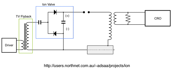
I thought an Ion Valve was just another word for a glo regulator. It isn't. Above is where I've redrawn the ion valve circuit from the itty-bitty graphic that Bruce supplied. I though an Ion Pump was a type of vacuum pump that can reduce the pressure in a container to about 1 nanopascal. It isn't (actually it is) If seen on these pages it refers to a High Voltage Generator.
I've soldered the Proof Of Concept circuit together (above) and pluged it in. My sparkgap is two needles from my wife's sewing box, and you can see what the other components look like.
I can get different types of sparks with different voltages and gap distances and in the following reports, will now describe the voltage across a non-inductive 150-ohm resistor at the secondary of an air-transformer.
Back to the top of this page
Spark Types.
The power is on and with the lowest voltage I can get from my HV, DC supply. I notice a blue glow from the sharp tips of the sparkgap. Increase the voltage and I see the blue grows and connects the ends of the needles. Not enough voltage for a real spark yet. Just ion flow.
With a bit more voltage I hear a hissing sound become louder and then a series of chaotic crackles. Now there is a noisy, unstable spark jumping around in the gap.
As I slowly increase the voltage, the chaotic spark becomes more stable and a tone rises in pitch until it reaches a point where it snaps and becomes quiet*. I can no longer hear any sound. The spark is still present, thick and stable. It moves around like its made of rubber.
*Could it be that the spark IS making a sound and I can't hear it? I used to be an audio engineer working in live entertainment. So if it was making a sound above 14KHz, I wouldn't know about it.
Back to the top of this page
Burst Timing.
Keep this in mind when looking at the bursts: The period of each oscillation envelope or noise burst in the graphs corresponds to the flyback transformer driving circuit. Bummer. It's not the steady DC supply I thought it was. Even though the ion valve is rectifiying the AC and filtering with the capacitor, it still has an AC component and it's these ripples on the DC that appear to be triggering the spark :-(
These waveforms will not be the same if using a continuous, steady DC supply like a Vandegaff generator or nuclear battery. Hmmm, I'd love to see what that looked like.
The graphs depict voltage across a 150 ohm, non-inductive resistor and connected as per the Proof Of Concept circuit. The air-core output transformer looks like this.
Various high voltages were obtained by varying the driver circuit's oscillation frequency between about 27KHz and 50KHz and, as you've just read in the previous paragrahs, that effects the burst timing. Different voltages were needed to obtain various spark discharge types. The flyback's fundamental resonance in all these configurations is 90KHz. Remember those ripples I spoke about earlier? Well they arn't pure sine ripples because of the harmonics generated by the differences in the driver's oscillation frequency and the flyback's fundamental resonance. More complications.
ALL current measurements were taken at the power supply for the driver, which is a real problem, partly because it includes the current drawn by the timebase oscillator but mainly because the faster the flyback's FET switching transistor, the less efficient it is.
Difficult to make accurate measurements on.
Back to the top of this page
Experiments.
The Rubbery, Silent Spark.
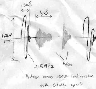
I don't have a digital camera. But I do have a pencil and scanner, so here is your crappy, hand-drawn scan.
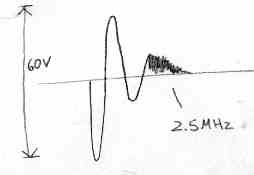
With the two needles adjusted to a distance of about 5mm, my sparkgap is silent* and continuous. I've got lots of voltage coming out of the generator. One end of the sparkgap is getting quite hot. Glowing red.
I put a ferrite slug into my air-core inductor and watched the 2.5MHz frequency drop, so this sine burst oscillation you see is a result of the inductor ringing. Even though I haven't used a capacitor, this is still a resonant circuit due to self capacitance.
The noise bursts are probably a result of the driver circuit resonating with a higher-than-normal harmonic content, thereby not reaching it's peak voltage everytime the flyback is 'plucked'. The flyback's fundamental resonance is at 90KHz
Considering the amount of current going in (1.2A) and the amount coming out (2uS of 1.2V + 10uS of noise at 0.8V), the only thing anomalous with this setup is where all the energy is going! lol
The Loud Spark.
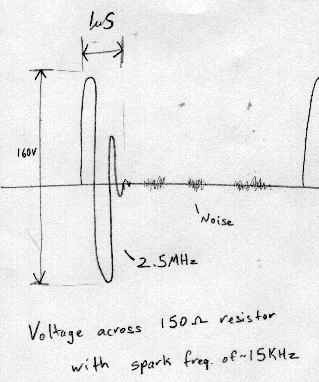
I've adjusted the sparkgap to 5mm and turned the pins around so that the thick ends face each other and the current draw is now 1.6A. This spark is making a tone at about 15KHz (the limit of my hearing).
A very fast envelope (1uS) of a 2.5MHz burst reaching 160V p-p across load. Something slightly weird here because if I short the load resistor, the voltage should go to zero but it doesn't. It goes to 20V p-p. And if I change the gain setting on the cro it changes again. Hey, if I remove the probe from the cro I still get a reading! Hmmm, lots of em radiation interferring with everything. So these readings are likely inaccurate.
No Spark.
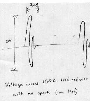
Now the sharp ends of my sparkgap are are facing each other again. The distance is much further - 17mm. I've reduced the voltage as current draw is now only 0.5A There's no spark just a thin blue glowing streamer in the gap. There's still a 2.5MHz burst at 8V p-p. Is this the pre-discharge oscillation that was reported?
Without the glo regulator
The regulator is shorted circuited. A thick, loud, powerful spark jumps chaotically in the 5mm gap. It's hard to get a stable image on the cro. Current draw at the supply was 1A.
Without the spark gap
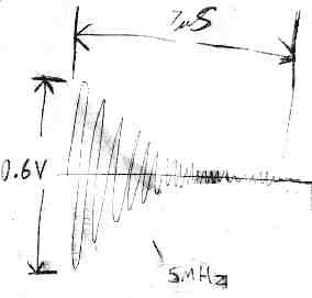
The spark gap has been replaced with one piece of copper wire. There is no spark because there is no gap. Current draw at the supply was 1A. The burst is now 5MHz ?
Back to the top of this page
The bottom line
Strange how I'm getting 8V p-p with No Spark. Investigatimg that further... I can't seem to replicate that result. Now I can only get about 2V p-p. Is this the pre-discharge oscillations reported by Ossie? One thing is sure - The Proof Of Concept circuit is extremely sensitive to just about everything. Especially the spark gap distance.
The glo regulator making the inductor ring with no sparkgap was interesting but not totally unexpected as the glo regulator makes a fabulous wide-band noise source which would make anything ring. I'd love to get hold of a Vandegaff generator (or nuclear battery) to play with.
Links.
I keep various interesting files that I have found in various places ;-) I usually forget where I saw something, so I usually rip-them off the website and save them to my hardrive and then it's just a drag-and-drop to ftp so you might like to have a look at some of them. As far as I know, they are all public domain but if you have a problem with me displaying them here, contact me and I will remove them.
See the parts I use for my experiments. Discovery and pre-discharge oscillations
Make a nuclear battery alloy
Glossary of atomic terms
Old Keelynet article 'coldfiss' from 1995
Back to the top of this page
Flops
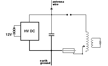
I've had a play with this circuit but didn't get much result. A feeble, noise-laden output where the antenna or ground connection didn't seem to make much difference. I experimented with putting the antenna and ground at different points in the circuit and found it did make a difference: The loading by the antenna and ground connections changed the resonant frequency of the flybck which in turn changed its frequency which in turn changed the voltage, which in turn changed the spark-type and burst envelope. I'm not very good with measurements at the best of times, so with this cascade of events it was a disaster trying to make sense of it.
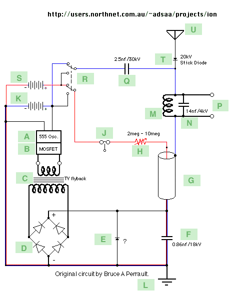
Don't build this circuit. It's the one I originally set-out to build but Bruce has told me that it won't work.
The reason is this capacitor [F] is much too large for a piss-little TV flyback transformer to charge. Silly me. It needs the higher current supplied by a microwave oven transformer to charge a microwave oven capacitor. Doh.